LCDInfo.com

http://www.lcdinfo.com
It is currently Wed Jun 26, 2024 9:15

All times are UTC + 2 hours


Post new topic Reply to topic  [ 8 posts ] 
Author Message
PostPosted: Wed Dec 22, 2004 2:14 
Offline

Joined: Fri May 21, 2004 0:00
Posts: 19
Hi

I need big help here. I started to work with the DG-16160-11-S1FTLY LCD

Datasheet: http://personal.nbnet.nb.ca/dunnbarr//DG-16160-11-S1FTLY.PDF


I tried to wire it like this:

Code:
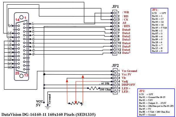
DataVision DG-16160-11 160x160 Pixels (SED133x)

JP1:

LCD    -> Description -> LPT
Pin 01 -> /WR         -> 1
Pin 02 -> /RD         -> 17
Pin 03 -> /CS         -> 14
Pin 04 -> A0          -> 16
Pin 05 -> /RES        -> 5 Volt
Pin 06 -> Data0       -> 2
Pin 07 -> Data1       -> 3
Pin 08 -> Data2       -> 4
Pin 19 -> Data3       -> 5
Pin 10 -> Data4       -> 6
Pin 11 -> Data5       -> 7
Pin 12 -> Data6       -> 8
Pin 13 -> Data7       -> 9

JP2:

LCD    -> Description -> LPT
Pin 01 -> Vss Ground  -> Ground Pin 18-25
Pin 02 -> Vcc         -> 5.0V
Pin 03 -> Vlc         -> Output: 0 .. -15.0V
Pin 04 -> Vadj        -> 10kOhm potentiometer to Pin 03 JP2
Pin 05 -> DISPOFF     -> 5V
Pin 06 -> LED +       -> 5 Volt + 100 Ohm Restistor
Pin 07 -> LED -       -> Ground

Wiring-Type: PowerLCD


Since i'm a visual man, I did this schema that I join.

Image

The problem is, well it doesn't work. The Contrast part don't work at all. So problem look to be in Pin 02 03 04 05 of JP2.

Also, look at the data sheet (again: http://personal.nbnet.nb.ca/dunnbarr//DG-1...-11-S1FTLY.PDF)

on Page 11, you can see the Pin 3 of JP2 being INPUT, not output.

Also look on Page 13 for voltage regulation. I simply don't get it.

Please help me. I have 2 of those LCD and would not like to burn any of them.


Top
 Profile  
 
 Post subject:
PostPosted: Wed Dec 22, 2004 6:01 
Offline
User avatar

Joined: Fri Dec 03, 2004 7:03
Posts: 201
Location: Sydney, Australia
The problem as I see it is the way you have connected the POT for the contrast adjustment. this pot needs one side conected to VCC, the other side to VLCD, and the wiper/adjusted pin connected to VADJ. Not connected as you have it as a variable resistor between VADJ and VLCD.

Image
Here you see my badly edited schematic.

_________________
Syridian,
http://syridian.com


Top
 Profile  
 
 Post subject:
PostPosted: Wed Dec 22, 2004 15:27 
Offline

Joined: Fri May 21, 2004 0:00
Posts: 19
well that sound logic.

I'm not very good at electronic so I could be wrong there.

I will try this
thanks

Edit: Beside that, everything seem ok ? (The Led is very dim, I will change the 100ohm for something smaller)


Top
 Profile  
 
 Post subject:
PostPosted: Thu Dec 23, 2004 2:17 
Offline
User avatar

Joined: Fri Dec 03, 2004 7:03
Posts: 201
Location: Sydney, Australia
100 Ohm should probably be 5 ohms, as most LCDs I have played with have built in resistors anyway... I didn't really spend too much time checking eveything else out... Thats your job. ;)

_________________
Syridian,
http://syridian.com


Top
 Profile  
 
 Post subject:
PostPosted: Thu Dec 23, 2004 20:48 
Offline

Joined: Fri May 21, 2004 0:00
Posts: 19
Well I fallowed your Schema.

Good thin is nothing seem to be overvolted (the LCD stay fairly cold)

But I still have no contrast at all (so I can't see anything)

I really don't know what to do. I tried the second LCD I had and same thing, so it's not a dead LCD (yet).

if you have any idea, it would be much apreciated.


Top
 Profile  
 
 Post subject:
PostPosted: Fri Dec 24, 2004 2:29 
Offline

Joined: Fri May 21, 2004 0:00
Posts: 19
finally I talked to someone that work with those lcd.

I need negative voltage on that LCD. This is why it isn't working.

I will try to find an easy way to get negative voltage


Top
 Profile  
 
 Post subject:
PostPosted: Sat Dec 25, 2004 1:47 
Offline
User avatar

Joined: Mon Oct 11, 2004 0:09
Posts: 17
Location: Hellas - Thessaloniki
you can use TC7660 It can give Vout = -Vin or Vout = 2Vin and its circuit is very easy.

and the best is that you can get a free sample ....ohhhh "free" , the magic word!

_________________
gsmaster :)


Top
 Profile  
 
 Post subject:
PostPosted: Mon Jan 31, 2005 16:46 
Offline

Joined: Fri May 21, 2004 0:00
Posts: 19
I ordered 3 chip that will give me -15V (to my information, this is what the LCD need) I should receive them this week.

Could someone review my schema and telle me if everything is fine ? I'm not really sure.

Thanks


Top
 Profile  
 
Display posts from previous:  Sort by  
Post new topic Reply to topic  [ 8 posts ] 

All times are UTC + 2 hours


Who is online

Users browsing this forum: Bing [Bot] and 14 guests


You cannot post new topics in this forum
You cannot reply to topics in this forum
You cannot edit your posts in this forum
You cannot delete your posts in this forum

Search for:
Jump to:  
cron
Powered by phpBB® Forum Software © phpBB Group