EDIT: Information below is wrong. Check following posts for explanation.
______
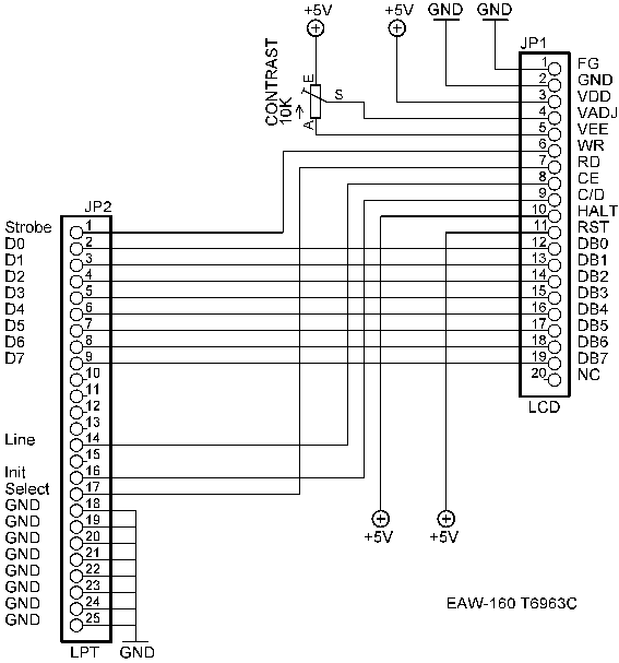
Now that I looked at the datasheet more carefully I noticed that the pinout is same as for the earlier display:
I didn't notice anything mentioned about the FS and MD pins.
I also have a paper copy of the specs so here are the backlight specifications:
Voltage: 4.1v (typ) 3.7v (min) 4.4v (max)
Current: 650mA
So you need some resistor for the backlight as 5v is too much. Calculating with those values I got 1.5 ohm for the resistor but I'd recommend trying with about 3 ohm at first and then smaller value if that's not bright enough (or larger value if the backlight becomes too hot).