LCDInfo.com http://forum.lcdinfo.com/ |
|
Crystalfontz CFAG12864B-YYH-N wiring help http://forum.lcdinfo.com/viewtopic.php?f=6&t=1164 |
Page 1 of 2 |
Author: | gweedo [ Tue Apr 19, 2005 19:22 ] |
Post subject: | Crystalfontz CFAG12864B-YYH-N wiring help |
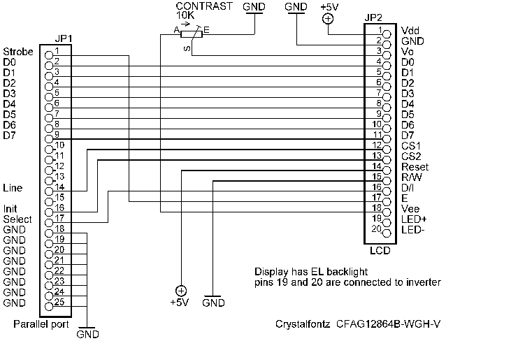
Hello, I just registered to the forums, although I've been lurking for a while. I recently bought a crystalfontz graphic lcd (CFAG12864B-YYH-N) and I'm trying to connect it to the parallel port. I don't know much about electronics, I just know how to follow a diagram (almost ), so I'm asking for help on how to wire this LCD i bought. Here's a picture of it and its electrical characteristics and pinout Can I use the same diagram as this one to wire it? Also, what if I wanted to put a pot to control the brightness? thanks for any help |
Author: | mingingbollock [ Tue Apr 19, 2005 21:26 ] |
Post subject: | |
Welcome to the forum mate, hope you enjoy your stay, i started on a little CF like that Yes wire away , you aint got the led voltage there , you WILL need a resistor in series there +, last one i wired used a 22r but i would check that pot and bightness control is possible, you can do the sums http://forums.bit-tech.net/showthread.php?t=61317 And for gods sake please use pcb headers on the lcd, dont solder the wires directly onto the lcd pcb its a nightmare fixing them http://www.crystalfontz.com/products/12 ... 4BYYHN.pdf |
Author: | gweedo [ Wed Apr 20, 2005 0:59 ] |
Post subject: | |
thanks for the tips. just a couple more questions pin 2 and 15 connect to ground, do I just leave them not connected or do i have to connect them to something? also I don't really understand that sentence on the bottom of the drawing where it says "Display has EL backlight pins 19 and 20 are connected to inverter" do I need to connect those pins? Also, here is the backlight information, what resistor should i use? Lastly, what are the A and K pins for? thanks, I think i should have studied electronics more when I was in high school -g |
Author: | coorz [ Wed Apr 20, 2005 12:27 ] |
Post subject: | |
Pin 2 & 15 should be connected to GROUND, that means the negative (-) side of your powersupply. Neglect the statement about EL, as your display has LED backlight. Resistor should be around 10 ~ 22 ohms (A) stands for Anode which is +5 volts (K) stands for Kathode which is GROUND (-) |
Author: | gweedo [ Wed Apr 20, 2005 20:35 ] |
Post subject: | |
Ok, thanks, I'm beginning to understand better I found this schematic on a website, and was wondering if I could use this one (I added the red writing). The pinout is the same as the YYH-N. From what I understand it has brightness and contrast control via the 1k and 10k pot's. a couple more questions: - can I connect all 5v wires to the red cable of a molex and all the ground ones to the black cable? - I don't really understand if I have to connect 19 and 20 or I have to connect the pins named A and K on the lcd to 5v and the pot. - On the schematic posted on this site pin 14 (reset) is connected directly to 5v, should I just connect it to 5v? What would be the difference? sorry for the many questions, but I just want to make sure I understand everything correctly before I start wiring the LCD here is the drawing i found |
Author: | coorz [ Wed Apr 20, 2005 21:29 ] |
Post subject: | |
- can I connect all 5v wires to the red cable of a molex and all the ground ones to the black cable? > Yes you can - I don't really understand if I have to connect 19 and 20 or I have to connect the pins named A and K on the lcd to 5v and the pot. > If correct they are internally wired, so pin 19 is the same as (A) and pin 20 is (K) so you can choose whether to wire to the header or the A/K pads - On the schematic posted on this site pin 14 (reset) is connected directly to 5v, should I just connect it to 5v? What would be the difference? > Yes it can go straight to +5v, |
Author: | gweedo [ Wed Apr 27, 2005 20:52 ] |
Post subject: | |
hello again, i wired the lcd using the schematics i posted, but it doesn't seem to work. I've tried many different programs including LCDinfo, but all I get is this screen, or a blank screen with only the led on also here is a drawing of how i wired the lcd, do you see anything wrong with it? I double checked it and it seems corresponding to the schematic, maybe I have messed something up while soldering. the contrast and brightness pot both work fine. Note that I connected the lcd molex to a test-PSU and the parallel cable to my pc, and turned both up at the same time, but I don't think that can be a problem. Any hint would be appreciated, before I start unsoldering and redoing everything. bye |
Author: | One~Zero [ Thu Apr 28, 2005 3:36 ] |
Post subject: | |
I don't see on you're wiring diagram where you input your -10v for the LCD drive voltage (as listed on the spec sheet). If you look on page 8 of the datasheet, it shows -10v to one side of the 10k pot, vo (pin 3 on your lcd) to the center of the pot, and vdd to the other side of the pot (I've actually seen people use either vdd or vss on this side...but on your data sheet it shows it to vdd...?) Also, the data sheet shows NC on pin 18...don't need to connect it. I would hold off until someone else validates what I'm saying though...just to make absolutely sure I want to make sure you need -10vdc...you may only need about -3vdc or so since the value shown on your spec sheet is Vdd-VO=8vdc |
Author: | One~Zero [ Sat Apr 30, 2005 22:55 ] |
Post subject: | |
I just noticed that you had said that your contrast works fine...Is there a negative voltage already generated on board? Is there a negative voltage present on pin 18 (VEE)? |
Author: | gweedo [ Mon May 02, 2005 12:26 ] |
Post subject: | |
sorry I don't have the knowledge to understand what you're talking about. I followed the schematic i posted above without understanding what I was doing. |
Author: | One~Zero [ Mon May 02, 2005 23:27 ] |
Post subject: | |
With your 5vdc and ground applied like you already have, check to see if you have a voltage on pin 18 of your display. If there is one (I would guess it to be about -10v) then that saves you having to provide one externally. If there is no voltage there, then you need to make up an external circuit to give you the -10vdc for your LCD bias and contrast adjustment. |
Author: | gweedo [ Fri May 06, 2005 12:19 ] |
Post subject: | |
i discovered the lcd has already negative voltage built in anyway i used the same wiring on another lcd of the same type, and i get the images but they are somewhat scrambled or shifted. I'm thinking it's some wiring problem, like I have switched 2 pins or something, could it be? here's what i get lcdinfo 0.3.1 cfag wintest ks0108 test |
Author: | One~Zero [ Sun May 08, 2005 4:05 ] |
Post subject: | |
Looking a lot better Make sure your screen size in LCDinfo is the same as the one for your actual screen. Looks like it is defaulting to a larger screen than what your display supports. Look at some of the "premade" xml files in lcdinfo, and try to load just one screen with your size first. |
Author: | coorz [ Sun May 08, 2005 9:15 ] |
Post subject: | |
Yeah your LCD looks alright. I believe there was this issue with KS0108 with wrong halves displayed. To solve this CS1 <>CS2 had to be switched. http://forum.lcdinfo.com/viewtopic.php? ... hlight=cs1 |
Author: | gweedo [ Mon May 09, 2005 17:37 ] |
Post subject: | |
switched CS1 and CS2 and it works great now thanks everybody for your help. |
Page 1 of 2 | All times are UTC + 2 hours |
Powered by phpBB® Forum Software © phpBB Group http://www.phpbb.com/ |