Hi!
I have bought a display ( 128 * 64 ) T6963C but how do i wire this display?
I have seen another wiring schema but they are all diferent.
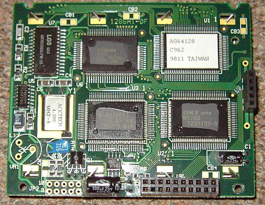
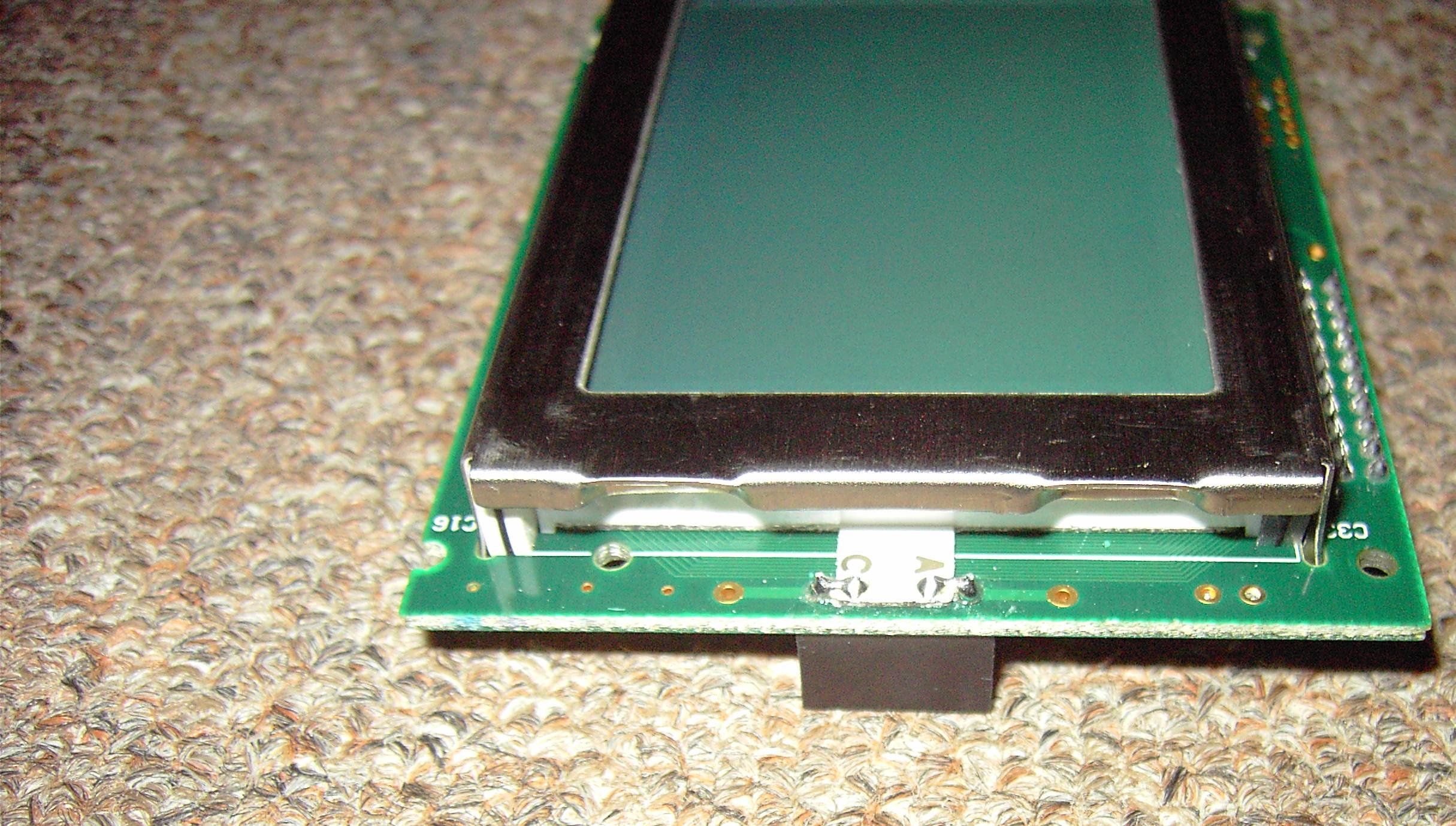
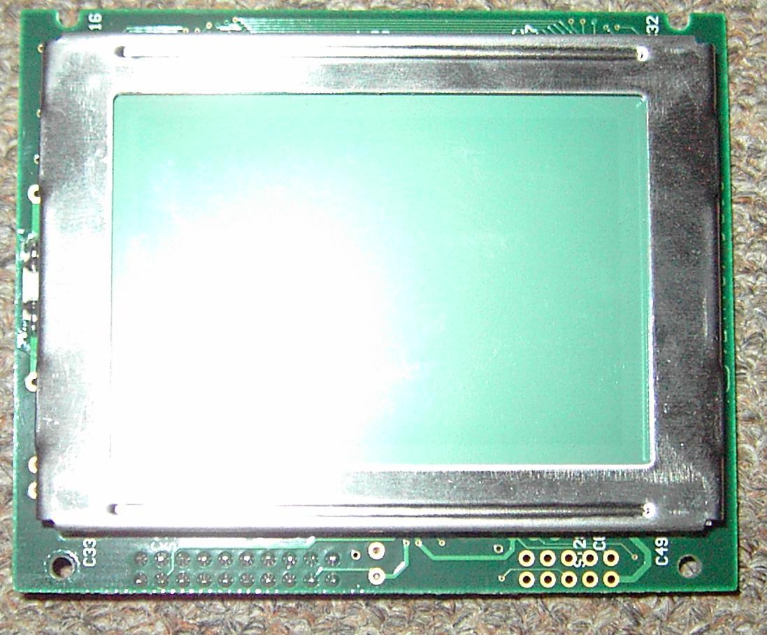
Here are some Pic's:
Thx
| LCDInfo.com http://forum.lcdinfo.com/ |
|
| T6963C Display http://forum.lcdinfo.com/viewtopic.php?f=6&t=1755 |
Page 1 of 1 |
| Author: | Akca [ Fri Oct 06, 2006 22:40 ] |
| Post subject: | T6963C Display |
Hi! I have bought a display ( 128 * 64 ) T6963C but how do i wire this display? I have seen another wiring schema but they are all diferent. Here are some Pic's:
Thx |
|
| Author: | Akca [ Wed Oct 11, 2006 15:53 ] |
| Post subject: | |
Hi I have used this schematic but it doesn't display anythink! I use the Power of from the USB. (+5V) 
anyone an idea? |
|
| Author: | Akca [ Thu Oct 12, 2006 7:42 ] |
| Post subject: | |
PLease I need help! |
|
| Author: | Zee [ Thu Oct 12, 2006 8:31 ] |
| Post subject: | |
If you can't find datasheets for the display your only option is the datasheet for the T6963C controller and a multimeter. You can then trace what signal from the controller is connected to which pin in the connector. Also, some of the displays with T6963C need negative voltage to get anything visible on the display. |
|
| Author: | Akca [ Thu Oct 12, 2006 17:23 ] |
| Post subject: | |
Wow! Thats a brilliant idea! I will try it! What do you think will happen if i connect unintentionly 2 pins of the controller? |
|
| Author: | Zee [ Thu Oct 12, 2006 19:10 ] |
| Post subject: | |
Older IC-technology (CMOS?) works in a way that if you leavel +5V from powerline disconnected and instead connect it to something else it usually is the end of that IC. In general it's a bad idea to feed voltages to where they do not belong to. Shortciruits are also to be avoided. |
|
| Author: | Akca [ Thu Oct 12, 2006 19:32 ] |
| Post subject: | |
OK i have traced back the signal from the connector to the controller and this cames out: T6963C Controller ------- Connector C/D --------------------------- 3 CE --------------------------- 15 RD --------------------------- 17 WR --------------------------- 6 D7 --------------------------- 14 D6 --------------------------- 13 D5 --------------------------- 12 D4 --------------------------- 11 D3 --------------------------- 10 D2 --------------------------- 9 D1 --------------------------- 8 D0 --------------------------- 7 Reset --------------------------- 16 Vss --------------------------- 1 Vdd --------------------------- 2 Okey! And now? What is with the other pins? 4, 5, 18, 19, 20 How do i now which pin is which connector for example the pin for the Contrast. |
|
| Author: | Zee [ Thu Oct 12, 2006 21:53 ] |
| Post subject: | |
Without knowing any better I'd start by tracing where the rest of the pins connect to. I'm only quite sure they are not connected to any of those 5 largest IC's. |
|
| Page 1 of 1 | All times are UTC + 2 hours |
| Powered by phpBB® Forum Software © phpBB Group http://www.phpbb.com/ |
|