Looking at this picture
http://img225.imageshack.us/my.php?imag ... 008tw3.jpg
the large square QFP chip is a TMP87C841U microcontroller. So it has a custom program in it that we don't know what it does. And the 30 pin connector and it's communication protocol isn't documented anywhere. And on top of that looks like the board has got quite rough handling so it probably would need fixing before it works.
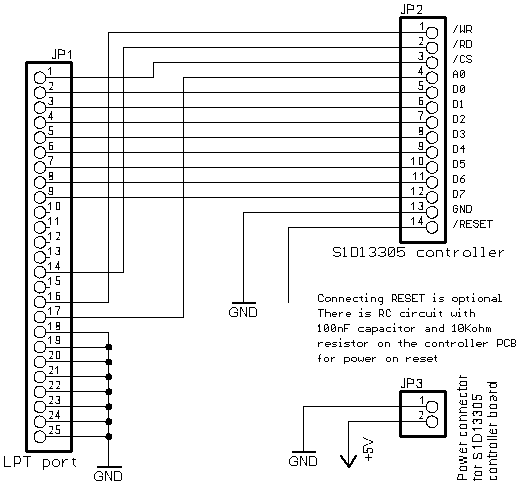
But that looks like a 320x240 pixel Sharp LCD panel and it has 12 pins. It might work with the S1D13305 controller board with 12 pin FFC connector from here:
http://www.skippari.net/forsale/
S1D13305 controller is also supported in the PC softwares that you would probably like to use.
This is the pinout that the controller has
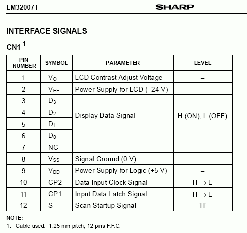
You could try measuring with a multimeter where the pins from the 12 pin connector on your board go and compare to the above pinout. First I'd check the power pins like VDD and GND and if those match then continue trying to figure out the rest. If the power pins match I think there's a pretty good chance the rest is in the same order too.