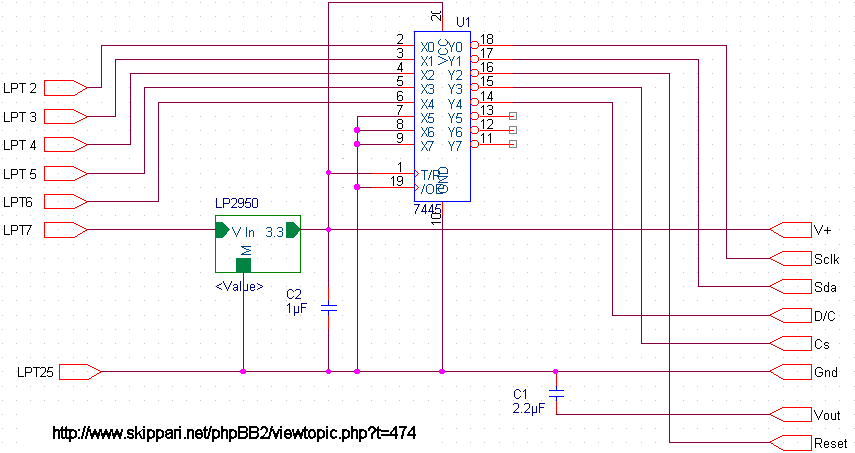
Henri, thanks for the reply. However, I still have some doubts (I'm sorry, but I want to fully understand this). Osc pin from the LCD must (or so I think) be connected to a PCD8544, however, no 8544 is present in the schematic:
or this schematic (very similar, but instead of using an embedded chip to convert logic voltages, uses R's and Zener diodes):

I may be doing a wrong assumption, which is that the right side pins on your schematic are not connected directly to the LCD, but to PCD8544, and then there would be several connections between PCD8544 and LCD (as stated in the PCD8544 .pdf sheet). I was making this assumption after reading a french tutorial about making 3310's screen work with LCDINFO without using PCD8544.
http://users.skynet.be/fa358153/david/t ... /index.htm
According to this article, it is possible to do it without PCD8544. I was wondering what would happen if LCDinfo could use one of the LPT port pins to output a 32Khz clock signal... could 5510's LCD be used as in the french guide?
Again, I thank on advance any tips or guidance that anybody can give.


