LCDInfo.com http://forum.lcdinfo.com/ |
|
Nokia color LCDs (Philips / Epson) http://forum.lcdinfo.com/viewtopic.php?f=9&t=586 |
Page 1 of 20 |
Author: | Henri [ Sat Apr 03, 2004 15:05 ] |
Post subject: | Nokia color LCDs (Philips / Epson) |
This topic is reserved for discussion about the Nokia phone color lcd displays. Nothing much to say here yet but this is for directing the discussion about these displays from other topics to here. Here's some datasheets: http://www.hantronix.com/down/S1D15G00_REV1_0.pdf http://www.semiconductors.philips.com/p ... 2DA_1.html There are two different display types that look almost same but have different controllers. I have had these from the beginning of this year but haven't yet started to work with them. But as they have the datasheets available it shouldn't be too difficult to make them work. |
Author: | Schijf [ Sat Apr 03, 2004 20:12 ] |
Post subject: | |
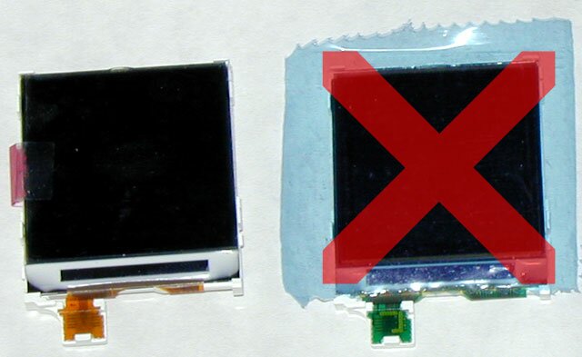
Ooooh, a nice clean topic to post my crap in Great you've made it Henri! Let's start by posting the info I've gathered so far. If anyone can knows more, please tell us as we LCD nutcases/programmers are always hungry for more! In our quest for easy to use, not to expensive, and not to hard to get colour LCDs there's finaly some light at the end of the tunnel. The Nokia phones housing the displays we're talking about are the 6610 and 7210. Both phones have a 128x128 display capable of showing 4096 colours. The display that is being used is either an Epson model or a Philips model. Although they are being used in the same phone, they have a different controller. The phone's firmware detects which display is attached to it (the displays have a hardwired ID). The Philips one uses the PCF8833 and the Epson a S1D15G00 compatible one (or so it seems). For datasheets, see henri's post above. So far so good, you'd think both displays are good to use. But... there seem to be a couple of problems with the Epson one. It's internal chargepump responds to light if the controller is not covered. This will cause the display to go 'on' as if there is to much voltage applied. Secondly, the Epson one is very picky when it comes to voltages and contrast. It's very hard to get the right contrast with a specific voltage. Both problems can be solved, but as the Philips hasn't got either of problem, why bother if you can avoid it. Also the documentation of Philips is better in my opinion. My advice is to use the Philips one and ignore the other. One more very important point is wether or not it's easy to solder. Looking at this, the Philips one wins bigtime as the display has 11 HUGE goldplated contacts (compared to usuall GSM parts ). Look at the photo and you know what I mean: There's also a second thing to keep in mind. The Philips one has a brown orange flexible PCB while the Epson's PCB colour is green. This is visible on the photo below (never mind the red cross I put over it ): Also this will take some extra hardware. You won't be able to just plug it into your parallel port. The display works best at 2,8V, the backlight at 6V and the parallel port with 5V signals. I've been thinking of taking a LM1117-ADJ low-drop voltage regulator to generate the 2,8V and a 74LVC4245 as level shifter. I don't know how easy the shifter can be gotten, but if that's to hard, I'm gonna try the 74LV245. And maybe the backlight will work fine at 5V, so no additional voltage regulation will be needed. Time will tell Please note that all this is just research so far, both henri and I haven't gotten around to actually test it yet! Most of the 'problem information' was figured out by some nice ppl on the Yampp discussion boards. They deserve credit for the initial discovery of the usability of these displays if I'm not mistaken.. |
Author: | Henri [ Tue Apr 06, 2004 19:47 ] |
Post subject: | |
Thanks for posting this nice summary about these displays. I'm sure many will find it useful. I don't really have anything to add at the moment until I get some first hand experience with these. LPT port isn't very fast in emulating SPI and it's limitations already begin to show with the PCD8544 display and with larger color display very fast speeds can't be achieved. Besides the LPT interface I have been planning to try interfacing the display with the bit-bang features of FT245BM/FT232BM chip to see if it would bring some more speed. Another solution might be taking some microcontroller with hardware SPI and attaching it to parallel port. Any other solutions that might be worth looking at ? The simpler, the better. |
Author: | Schijf [ Wed Apr 07, 2004 9:33 ] |
Post subject: | |
Good point! The display itself would be able to process rougly 30 frames/sec (not taking commands into account, only 12-bit colour databytes and C/D bit). But the LPT would never be able to spit out the data that fast. If the parallel interface of the controller was connected to the outside world, it might be workable for moving images... but alas, only SPI is available to connect to... and LPT would still be a little to slow.. The FT245BM would be a nice solution, but that would be a problem for some people (availability and small size). I wouldn't go for the serial version as that won't be sufficient either for applications like LiQuiD-MP3. I like the controller idea though. Not the best solution, but pretty simple and sufficient for almost all applications I think. Also this would probably have some limit. It would depend on the used controller and crystal, but a SCLK cycleperiod of 150ns (max of the PCF8833) is still 50ns faster than the instruction execution time of a 20MHz PIC controller. Besides that it would take multiple clock cycles of the PIC to send and receive 1 byte, so actuall speed will be much lower than the max of the display. For testing purposes I'm gonna try to connect it directly to LPT in combination with some zenerdiodes to get the voltage down to tolerable levels. That won't solve the speed problem, but it's good enough for static images to see if the driver works. |
Author: | Schijf [ Thu Apr 08, 2004 13:13 ] |
Post subject: | |
Hmmz, forget about the zenerdiodes. I thought (sh*t happens ) about the USB option last night and realized the FT245 has a dual powersupply! So no level shifter would be needed as the chip itself would run on 5V and with VCCIO tied to 3,3V all IO will have usable levels. The (Philips) display can run on the same voltage, so only a low drop voltage regulator would be needed. Power can be drawn from the USB, so no external powercables. The display can be powered by the databus of the FT245. The IO lines have a max current of 24 mA, and the display uses much less. However, this will not power the backlight. Btw, does anyone know the Fosc value for these displays? If it's not clocked at max speed it might be even possible to drop the voltage regulator and use the internal 3,3V regulator of the FT245. It can deliver max 5 mA, so it will be very close... |
Author: | Henri [ Thu Apr 08, 2004 14:28 ] |
Post subject: | |
Yes, the possibity for 3.3V IO was one thing that made me like the FT245BM solution. Forgot to mention this. If I remember correctly the older FT245AM chip didn't have this feature. And if the voltage regulator could be dropped it would make the circuit even more simple. And who knows, maybe the backlight would also work at 5V... |
Author: | Schijf [ Thu Apr 08, 2004 14:51 ] |
Post subject: | |
Just looked it up to be sure, the AM version does not have this version. But no matter, that chip is outdated anyways Btw, the backlight draws ~15 mA, so no problem there hooking it upto the 5V line on the USB. Wouldn't even need an EEPROM (although it would be very nice if the display is recognized as colour LCD instead of high speed serial device ). |
Author: | Schijf [ Sat Apr 10, 2004 1:15 ] |
Post subject: | |
Just completed a first crappy test to see how hard it would be to do. Here's the result: It's just a simple test with colours being generated from the x and y coordinates, so nothing spectacular. The entire image takes about 50 seconds to complete, but each byte uses 1 USB packet (worst case scenario...). So this can be hugely improved! The data throughput can be upped as well to further improve it. Also the default is 4096 colours, so switching to 256 colours will speed it up even more. Furthermore, be very carefull during soldering. The contacts are very sensitive to (I guess) pressure. I wrecked one of the LED contacts. Repearable, but you don't want this to happen. For the same reason I'm holding it to the light (silver 'backplate' removed)... Secondly, the solderislands are so close together that the solder will flow from one island to another, even if you use very little solder. So be sure to measure for shortages before applying power. Btw, if you're interrested in the schematic, let me know and I'll make one to put online. Oh and there are 2 pinouts to be found on the internet. One has the LED connections switched. The correct LED connections are: pin 9 - LED K (-) pin 10 - LED A (+) |
Author: | Schijf [ Sat Apr 10, 2004 15:05 ] |
Post subject: | |
Rerouted the backlight wiring, so the backlight works again normaly 5V is not enough. You can see the LEDs through the flex PCB, but it is almost impossible to see from the front (in the dark that is). So a higher voltage is needed. Maybe a simple step-up converter will work. That way we don't need an extra power supply. Just use the 5V from USB and up it 1 and a half volt or so... |
Author: | Henri [ Sat Apr 10, 2004 19:31 ] |
Post subject: | |
Congratulations! Now I need to put something together soon to keep up with you Did you use the 3.3V from the FT245BM or extra voltage regulator to power the display ? Also I'd be interested to know which display pin you connected to which FT245BM pin to keep our hardware compatible. |
Author: | Schijf [ Sun Apr 11, 2004 15:38 ] |
Post subject: | |
LOL, no rush, I'm just doing some tests. It'll be a long time before I'll release some sort of LiQuiD-MP3 Colour. There are bugs in the black and white version that need to be fixed first.. So take a beer, put on some good music and relax To be sure there wouldn't be any powerproblems (the 5 mA from the 245BM is pretty tight) I took my laboratory power supply and hooked it up. So instead of 5 mA there's 2A available hehe... huge overkill, but functional I ordered a couple of LM1117-3V3 regulators and once they arrive, one of them will replace the lab power supply. For the wiring, click here and the wiring should be clear. Some good news; Without to much tweaking the time needed to display a fullscreen image has been reduced from 50 sec to approx 1 sec! In 12-bit colour that is To reduce this time any further, adjusting the USB packet size might work, adjusting the buffer latency in the 245BM might work, and so on. But I think the biggest gain would be from switching to 8-bit colour, although I do like to have 12-bit colour. But this is something I personally haven't decided on yet. |
Author: | Karel [ Mon Apr 12, 2004 9:48 ] |
Post subject: | |
It looks really impressive. To speed up the display couldn't you use a dedicated MCU like atmel or PIC to build the image? Write some code to update only the ram in the controller? I'm currently working on driving an o-led display without controller and sofar it looks promising. Where did you get the displays because I would like to try ? |
Author: | Schijf [ Mon Apr 12, 2004 18:12 ] |
Post subject: | |
Some more test photos These displays are just plain cool! That's all I can think off right now |
Author: | Henri [ Mon Apr 12, 2004 22:53 ] |
Post subject: | |
Cool indeed! It seems that you're deliberately forcing me to put my display to work. It will be a long time before there will be a color LCDInfo either, if one ever comes. But just making the display work would be cool like you probably already know. |
Author: | Henri [ Mon Apr 12, 2004 23:01 ] |
Post subject: | |
Karel wrote: To speed up the display couldn't you use a dedicated MCU like atmel or PIC to build the image? It's possible and most likely will be tested later but the idea is to make it work with the least part count possible. Quote: Where did you get the displays because I would like to try ?
I got mine from a shop selling phone spare parts in Finland. Also www.jelu.se sells them but they are quite pricey there - at least to my liking. |
Page 1 of 20 | All times are UTC + 2 hours |
Powered by phpBB® Forum Software © phpBB Group http://www.phpbb.com/ |